CHIPTUNES?
YOU HAD MEAT CHIPS
I wanted that to say “you had me at chips”, because chips are delicious, but the typo is hilarious, and on this stain of a website it will stay forever.
Alright enough of that dumb stuff, lets talk real smart stuff. jakkplug crushes 24/7, lets just be honest. Mad shouts to ya’ girl Emilie Gillet, remixes ain’t possible without those DIRTY GOOD foundations. Sorry, OK, lets do buildings.
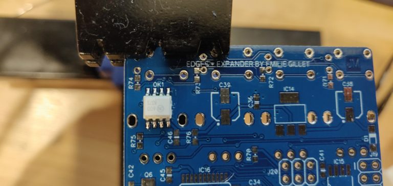
As always, I get the ICs down first. I’m sure I’ve explained this before, but getting all these finicky components in first gives you the space you need to get these pricier components in properly. That being said, keep your eyes peeled. Sometimes there are reasons to solder smaller components first, like some SMD resistors underneath an IC socket.
Really, the first thing I do isn’t get the ICs down. I stare at the PCB and decide what my plan of attack is. That’s the best move, but generally the best plan involves ICs first.
Another little tip from my little brain, if you have some fine pitch soldering to do, MCUs or weird connectors, solder an easier IC somewhere far from the harder component. This will get you used to how the particular PCB you are working on “feels” to solder. This is a strange concept and I can’t properly explain it with 26 letters, but if you’ve ever melted metal on to metal then you’ll feel what I’m puttin’ out there. If you haven’t melted metal on metal… just trust me and think of it as the equivalent of “warming up”. TRUST ME YOUNG ONE.
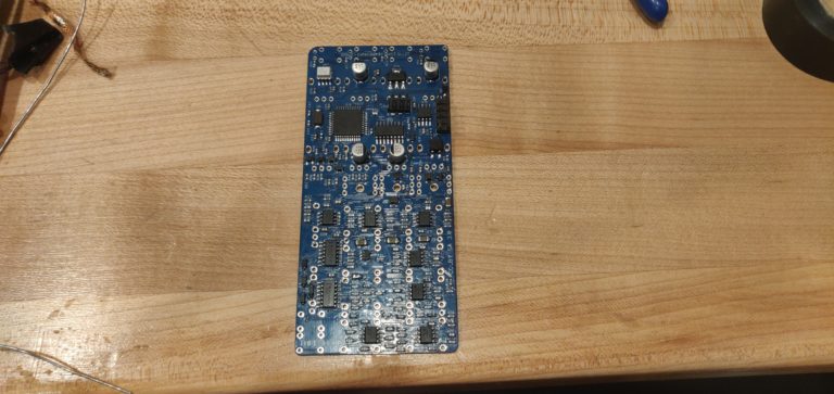
And then it’s done! Well… at least mostly. I have realized these build diaries are mostly me repeating the same things between slightly different projects. I will try to keep it more to the sillies and the more helpful things I found during the build. And pictures! Glorious pictures.
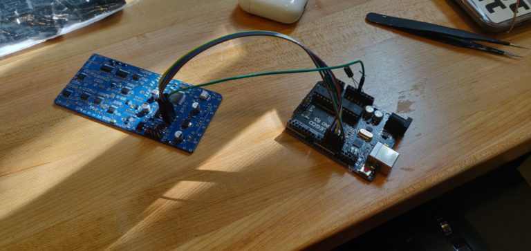
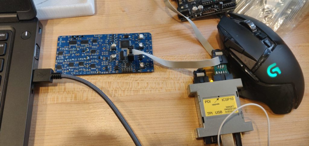
Sadly, my trusty Arduino couldn’t flash this bad boy. I ended up pulling out my AVR ISP MK-2 with a little 10 pin to 6 pin adapter, which is essentially doing this:

After getting everything connected, I ensured my programmer was powering the chip properly. I ended up using Atmel Studio to flash the bootloader, firmware, and set the fuses. This was the method that worked for me. Couldn’t seem to flash this with avrdude and my handy arduino.
Ready for the closeup?
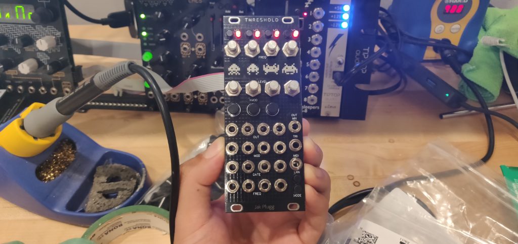
OK so it looks really silly with the alpha pots because they are FARRRR too big. I should have thought this through a little more before getting excited and soldering all 8 pots. And if you thought this looked silly, check it out with some knob action…
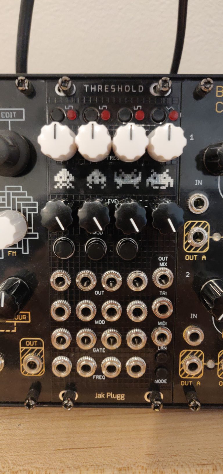
That’s OK though. I ended up ripping the knobs off and just marked the position with sharpie. The pots look like hell, but the second one turned out nice. Some nice skinny trimmer style pots really make this thing shine. Maybe if I payed closer attention I’d have done it right the first time, but here we are. Both sound identical, one has terrifying metal nipples.
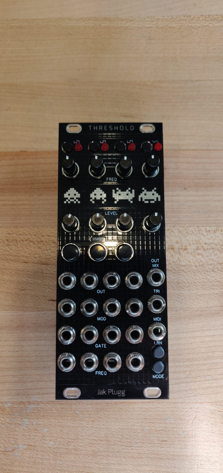
The module is really nice though, it has a very harsh digital sound. Rounds out really nice with a filter and some reverb, very very nice. The MIDI expander is a treat, you can get chords going with one cable. I will be keeping one of these in my rig for some time. You can’t beat 4 oscillators with individual frequency/modulation/gate control in one cute little 10hp package. Crushing it as always jakplugg.
That’s all folks! Stay tuned, more build diaries coming. What else should I be doing? Is anyone reading this? Send me an email, leave me a comment. More of my own projects? More of these build diaries? Video content? I don’t know!
Quick Links
Mouser BOM – No Pots/Jacks (you. need a stereo thonkiconn for the 3.5mm MIDI Jack)
BOMs be acting up. I’ll reupload my BOM if I can sort out how they got mixed up.
