Sunday fun-day time people, GET READY FOR A DIY CV TO MIDI BLOGGGGGGG.
This week we’re talking about some cute little CV to MIDI boxes my friend Herman Kolgen has me building for him. Credit goes to one Jean Phillipe Pierre-Louis (I heard he goes by Pipo, which is a fantastic nickname) for pretty much everything to do with these little guys.

So what the fun is going on here? I hear you my silly little readers, and I will explain!
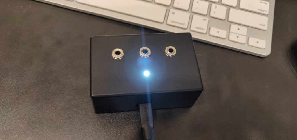
This is a little box with a Teensy 3.2 inside. The Teensy has 3.5mm jacks hooked into its analog inputs, and a cute little light to let you know that the thing is powered up and on. Then, a little coding magic translates the CV received on one end into MIDI CC values on the other end.
It isn’t meant for very hot signals. But it is great for plugging a sustain pedal into to get MIDI values, or a photoresistor on the end of a patch cable.
Fun, right? Here’s a little protoboard diagram for all you whacky SDIYers out there.

Something to keep in mind is that there is no protection (on this version) on the input jacks. You can’t pump any signal hotter than 5 volts into it, or you’ll fry it.
Also, it really can only understand differences in signals between 0v-3.3v. Not great for shoving 10v bi-polar LFO signals into. Trim and/or rectify your signals if you plan on doing something whacky like this!
Buildin' the DIY CV to MIDI bad boy
It is a fairly simple build, but here’s a quick BOM just in case the cute little protoboard layout is tough to read.
1 – Teensy 3.2
3 – 3.5mm Mono Jacks (Thonkiconn’s are good)
3 – 10k resistors
1 – 330 ohm resistor
1 – LED
Hook up wire
Protoboard
Housing
Not so bad. Something to clamp down the voltage and protect the inputs would be nice, but that is for another day and another iteration of this project.

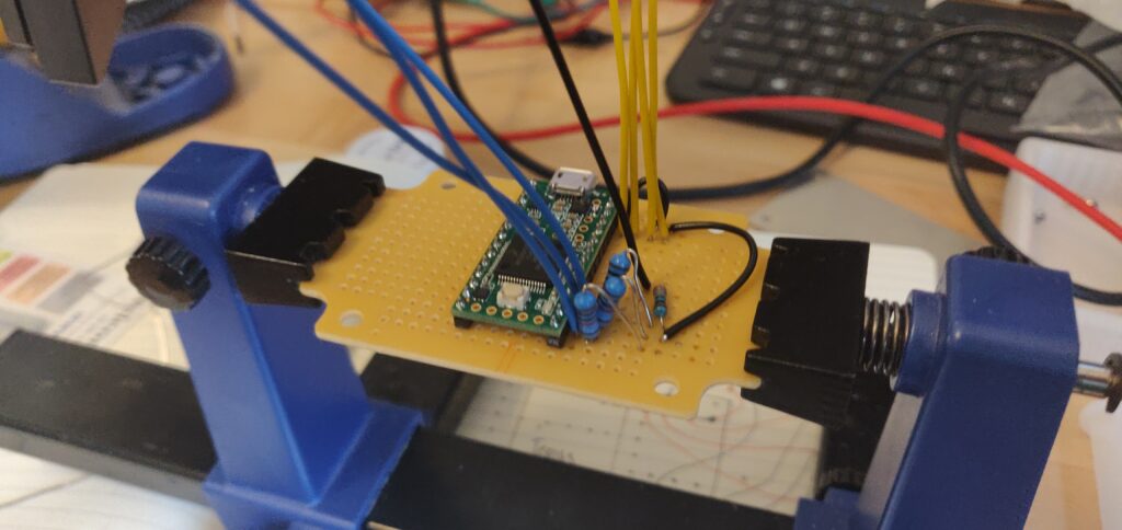
I was given these neat little project boxes to fit everything into, and it even comes with a slice of protoboard that fits perfectly inside the housing! Nice.
After some solder here, and a little flux there, we have something resembling our protoboard layout diagram!

I know what you’re thinking my curious little reader. What does it look like on the underside? Well this is a PG rated blog, OK? So you settle down.
Just kidding, here it is.

Lookin’ good! After everything was all wired up and ready to go, it was time to blow some holes out of the boxes!
I used a 1/8 drill bit for the LED. A 15/64 drill bit for the 3.5mm jacks. And finally a big old 15/32 drill bit for the USB port access hole.

And that about does it! It’s a very neat little idea, and very simply executed, which I appreciate. Sure, it doesn’t scale down voltages or anything wild, but there’s literally 6 components in the BOM. If I get a chance, I will modify this circuit slightly to protect the inputs so you can shove whatever you want in here, but for now, this will do!
The Computery Bits
Last but certainly not least, the Teensy is the brains behind this operation, and without any code, these brains are completely empty! So here is some of that sweet sweet C language for all you nerds out there.
/* CONNECTIONS

TEENSY KONTROL
A0 photoresistor 1
A1 photoresistor 2
A2 photoresistor 3

*/

// the MIDI channel number to send messages
const int channel = 1;

// the MIDI continuous controller for each analog input
const int controller_n1 = 71; //LDR 1
const int controller_n2 = 72; //LDR 2
const int controller_n3 = 73; //LDR 3

const int seuil = 30;

void setup() {

analogReadRes(12);// 12bit entree analogique
}

// store previously sent values, to detect changes
int previous_n1 = -1;
int previous_n2 = -1;
int previous_n3 = -1;

elapsedMillis msec = 0;

void loop() {
// only check the analog inputs 50 times per second,
// to prevent a flood of MIDI messages
if (msec >= 20) {
msec = 0;

int n1 = analogRead(A0);
int n2 = analogRead(A1);
int n3 = analogRead(A2);

//
//
//Serial.print(n1); Serial.print(' ');
//Serial.print(n2); Serial.print(' ');
//Serial.print(n3); Serial.print(' ');
//Serial.print(n4); Serial.print(' ');
//Serial.print(nLx); Serial.print(' ');
//Serial.print(nLy); Serial.print(' ');
//Serial.print(nRx); Serial.print(' ');
//Serial.println(nRy);

//delay(100);


// only transmit MIDI messages if analog input changed
if (abs(previous_n1 - n1) > seuil) {
if (n1 != previous_n1) {
int LDR_1= constrain((n1-seuil) / 32., 0, 127);
usbMIDI.sendControlChange(controller_n1, LDR_1, channel);
previous_n1 = n1;
}
}

if (abs(previous_n2 - n2) > seuil) {
if (n2 != previous_n2) {
int LDR_2= constrain((n2-seuil) / 32., 0, 127);
usbMIDI.sendControlChange(controller_n2, LDR_2, channel);
previous_n2 = n2;
}
}

if (abs(previous_n3 - n3) > seuil) {
if (n3 != previous_n3) {
int LDR_3= constrain((n3-seuil) / 32., 0, 127);
usbMIDI.sendControlChange(controller_n3, LDR_3, channel);
previous_n3 = n3;
}
}

}

// MIDI Controllers should discard incoming MIDI messages.
// http://forum.pjrc.com/threads/24179-Teensy-3-Ableton-Analog-CC-causes-midi-crash
while (usbMIDI.read()) {
// ignore incoming messages
// Credit: Jean Phillipe Pierre-Louis

}
}
This will get you 3 inputs, you can also modify the channel the CC messages are coming out on the USB end. In the above example the CC messages are coming out of 71, 72, and 73. The next set of boxes I’m pumping out will have 6 inputs! Just a few more jacks and some slightly modified code is all it takes.
And that’s about it folks! A quick little CV to MIDI box for the masses. Thank you to Herman and Jean Phillipe for being the brains behind this project. I wanted to type it all up so that anyone who had use for something like this could throw one together as well. Feel free to reach out if you have any questions!
Oh one last thing before I leave you out in the SDIY cold for the week. Deckard’s Dream is coming along just dandy, but this voice board had my eyes bleeding… Tell me if you can spot the issue here.

If you can’t tell, R161 looks a little more like R181. I must have looked around this board for 30 minutes before I got smart and pulled out one of the other voice boards to find R161. These are the trials and tribulations of polyphonic DIY synth goodness, but we’ll get there one day! Maybe. Most likely.
As always, thanks for dropping in and peeping my humble little slice of internet pie. Hope it was informative, or at the very least entertaining! If you’re looking for some more SDIY fun, check out some of my older posts, maybe a classic like the Build Diary #3: Faderbank 16n, which feels like it was written in a prior life, or maybe something more recent, like the LoFi-nator pedal build!
Either which way, have yourself a beauty week out there, and keep it samesies!

I’ve been loving reading your blog! Keep it up ya ol champ.
You’re making my weekend saying things like that Sjoerd.
I’ll keep pumpin’ em out, thank you way too much for reading!