And that was that! One thing that was strange, the firmware version I linked to here was.. out of tune? It sounded awful, but the functionality was all there. So before I hit the panic button, I downloaded the most recent firmware directly from the 4MS website and installed it via WAV file. And VOILA!
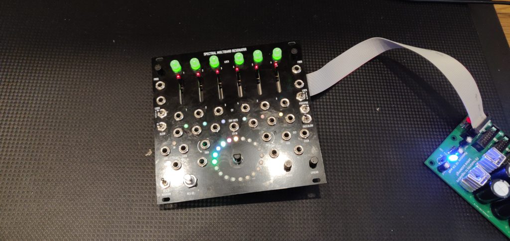
Only other issue I’ve run into is completely cosmetic, but the scale banks are not “coloured” properly when you select them. For example, in the manual, the Major Scale chord bank should appear as the first blue option in the selection menu. On my SMR, the Major Scale chord bank is the first selection in the green menu.
Oh actually one more issue, it’s so neat I’ve been shoving it into every sound I’ve been making lately… It really is spooky.
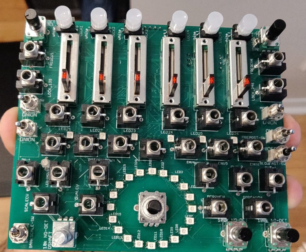
All in all this was a fun build, but it really took time. Next SMR (or possibly SWN?!?) will be solder pasted and reflowed. FOR SURE.
As far as how the module is, it’s great. For eerie ambience, fun percussive tones, or processing other tones, this little behemoth does a ton of good stuff. It’s a little on the large side, but what do you expect? It can even do some whacky VCO sequencing, and whatever a “Hexaphonic VCO Controller” does! COOL.
What next?! For sure some videos, no one reads anything ever.
And also… TELETYPE BUILD SOON! WHO IS PUMPED? THE SILENCE IS DEAFENING.
Quick Links
Mouser BOM – No Jacks, USB Port, or Pushbuttons. Actually, this BOM seems to be missing a lot of components. Will update in near future. For now, here are two other BOMs that have the goods.
MORE COMPLETE MOUSER BOM – Thank you muffwiggler user synchromesh.
MORE COMPLETE OCTOPART BOM – Thank you muffwiggler user synchromesh.
Muffwiggler Thread
SMR Product Page
Marcus Korb’s SMR Firmware


Really enjoyed reading about your adventure, as I’m thinking of having a crack at this project.
Where did you get the PCB?
Thanks for reading, I really appreciate it! I grabbed the PCB from Pusherman at this link right here. They’re still in stock, but if for some reason you can’t get a hold of one, let me know. I have a couple left over, and I’d be happy to share!
This is a really good build blog with all the information anyone would need to build an SMR module. I really enjoyed reading about your journey and I raise a glass. Word round the campfire is the SMR is the toughest diy build.
Making me blush out here, thank you for reading, and thank you even more for your comment! I will keep the diaries coming. The density of the board made it one of the toughest solder jobs I’ve come up against. Absolutely do-able though, just have to go slow! SWN will be getting it’s own treatment one day soon. Thanks again!
Hey, great blog, thanks for posting this.
Im starting mine tomorrow 🙂
Looking forward to your swn build.
And…sorry to give you `bad news` but reflowing a board like this….you got yo know what you are doin (which im not) i have actually failed badly at reflowing…so for know i trust my eyes, scope and iron
!
Cheers
Thanks for reading!! And that’s great, it’s an awesome module and you’ll have a blast building it. As soon as I can snag a PCB for the SWN I will be right on top of it, stay tuned!
Yeah now that you mention it, blowing hot air or baking a board like this would be terrifying. I’d end up with resistor arrays I didn’t want with my luck…
Take care and let me know how the SMR build goes!!
Awesome build, a quick question:
Do you happen to have a link to the push buttons, i don’t seem to find them in the BOM.
thank you.
Thanks for reading!! Strange they didn’t make it my BOM…thanks for spotting that! Here is a link, I will update my links in the post so they are included!
Pushbutton Mouser Link
After going back in, looks like my BOM is missing a whole bunch. I added two other BOMs that should round things out I will update my BOM later tonight! Sorry about that!
Hi Steve,
Congrats to this successful build! You motivated me to take my SMD skills to the next and give this a try. 🙂
If possible, could you please elaborate on how you managed to flash the firmware using a *.wav-file instead of *.hex? Tbh, I didn’t even know that is possible…
Thanks so much
Thanks for the kind words!!
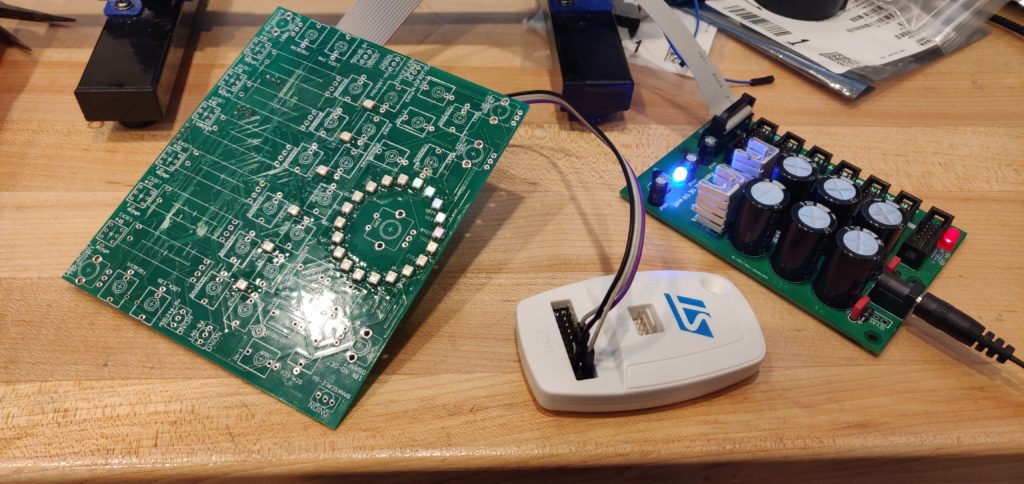
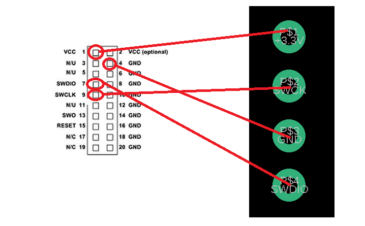
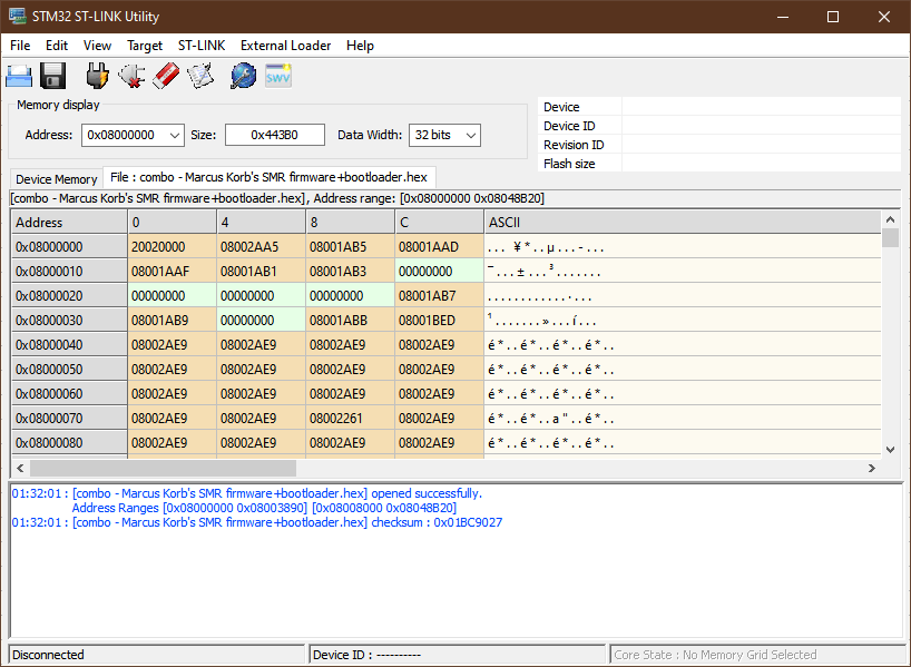
The initial flash has to occur over SWD with a good old fashioned “.hex” file. Once this is complete you can flash via WAV file using the method outlined in the manual here:
SMR Manual
Hey Steve, thanks for this blog, it really helps out building it!
I had read in the past that the footprint of the LEDs in the Mouser cart had a different order than the ones used in the real factory SMRs. Maybe there’s a way to change a couple of constants in the code to make the colours coincide with the original ones.
I’ll start trying that when I finish constructing mine.
Thanks for the comment Daniel! And that would be great, it is weird trying to match the banks as they are currently. Let me know how your build goes, best of luck!
Hello, a quick question, perhaps a bit off-point from your wonderful blog, but I figured you might know this one easily given your familiarity with the circuit – the production version of the SMR has individual envelopes out, and also an output of the 6 bands mixed together – but I do not see that it is possible to have individual audio outputs of the six signals. Perhaps I am misunderstanding the module and I need to RTFM, but is there any way to get six individual audio outputs – for example, by hacking into the device somewhere in the circuit where the six signals mix together prior to the physical output? This type of hack would open up so many possibilities for individual sound manipulation, but perhaps that is simply not how this circuit works? Apologies if I am misunderstanding or if there is a simple answer online that I have missed. Thank you for your time.