Who doesn’t love VCAs? They’re the vanilla ice cream of Eurorack, and boy does Mutable Instruments know how to add sprinkles. We’re talking Frames, but not Frames, Plancks. And not just Plancks, but Plancks II, by Jak Plugg. Let’s get into it.
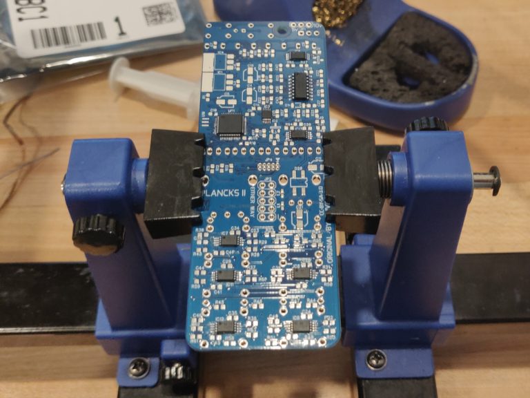
First thing first, gotta get all the ICs nice and soldered up. I generally go from lowest profile components to the biggest and bulkiest, beginning with the ICs, then moving onto the SMD resistors and capacitors, then the other components like diodes and electrolytic capacitors, and finally the hardware.
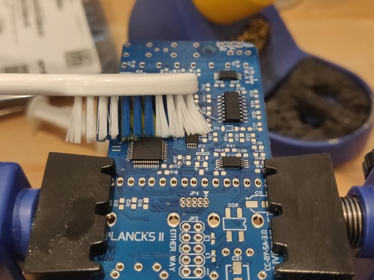
After the ICs, I like to give the board a little brushy brush. I take some rubbing alcohol and a toothbrush and give the board a nice scrub.
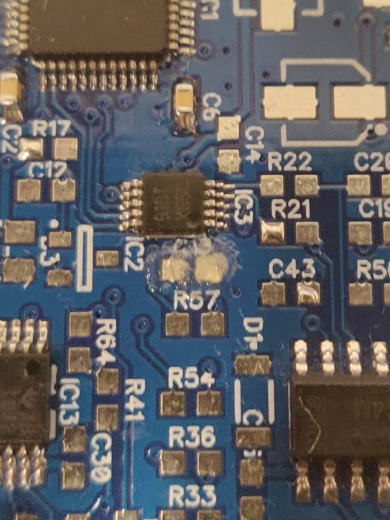
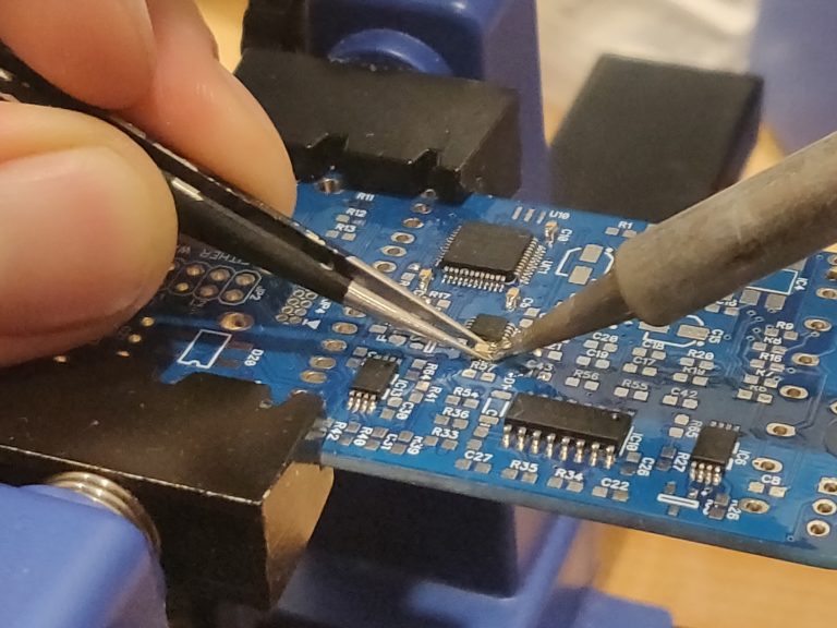
I then move on to the capacitors. I prefer to do these boards by hand with a soldering iron rather than reflowing. Feels more badass. Here is my badass method for soldering these tiny little parts.
Put some flux paste on the pad you’re soldering
2. Place component in flux, the flux will keep it there
3. Put a bit of solder on the tip of the iron, holding the component with tweezers in the left hand, push the soldering iron’s tip mostly on the pad, but touching the edge of the component as well.
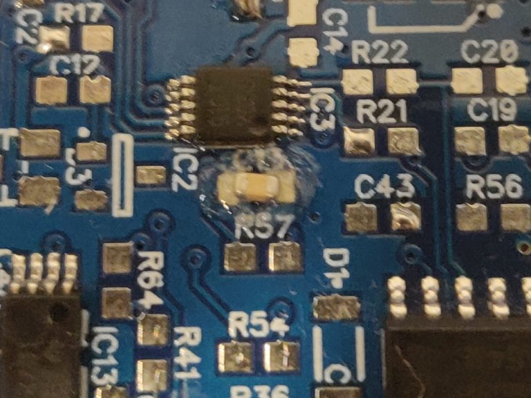
4. Now that the component is soldered on one side, put a bit more solder on the tip (unless there is some still left over), and press on the pad/component once again
5. I use no clean flux paste and no clean Kester Solder, but I still like to give the soldered components a wipe with rubbing alcohol and paper towel, keep it clean
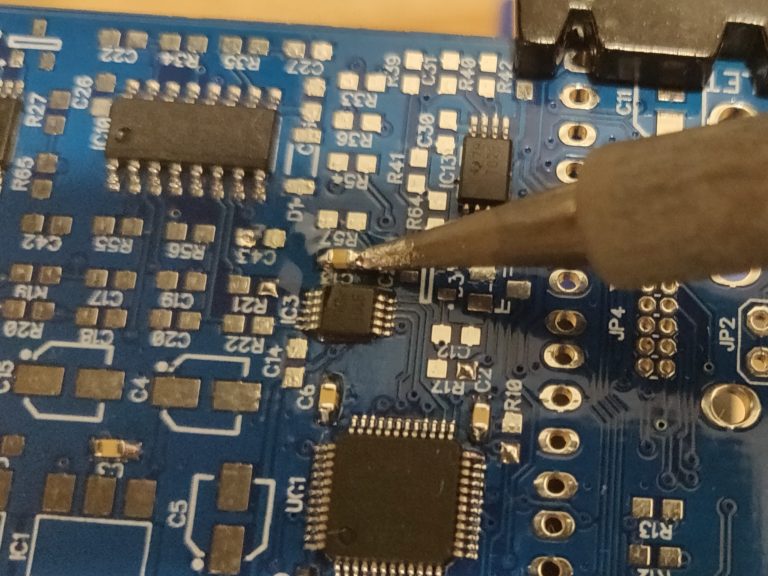
Then I get all of those capacitors in there. I like to do these components about 5 at a time, sometimes a little more or less depending on how many components of a certain value are left to do. Any more than this I forget to solder one of the pads, or miss them altogether.
Then I get all of those resistors in there.
Now that all of the 0603 sized components are in there, I bust out a slightly larger soldering tip and finish soldering the rest of the components. Electrolytic caps, diodes, resonators, ferrite beads, voltage regulators etc…
The scary part happens next. This is where I find out if the past 4 hours of soldering went well, or terrible. After a visual inspection, I pull out the multimeter checking for shorts/continuity that shouldn’t be there. Then, I add power, and pray there won’t be any smoke… Luckily, we’re not starting a fire with this one!
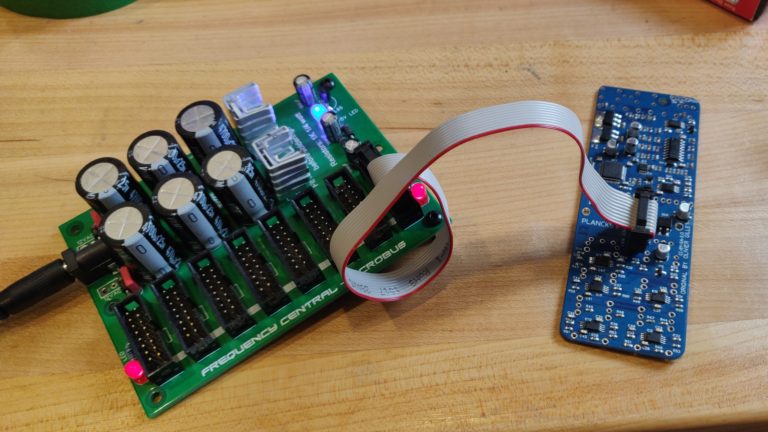
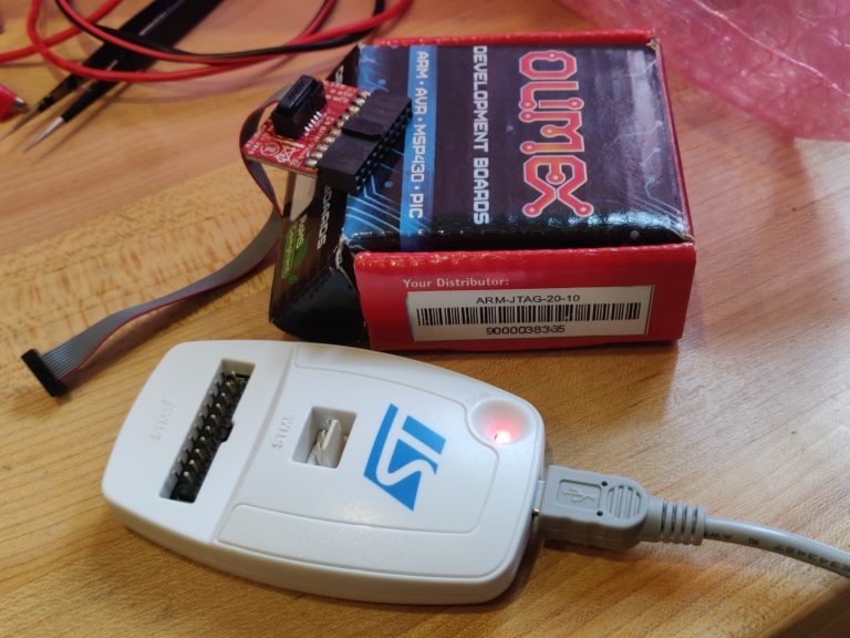
Next, I use an ST-LINK V2 with an ARM-20-10 JTAG adapter to flash the firmware on to the MCU. Let’s hope we can get the firmware onto this bad boy.
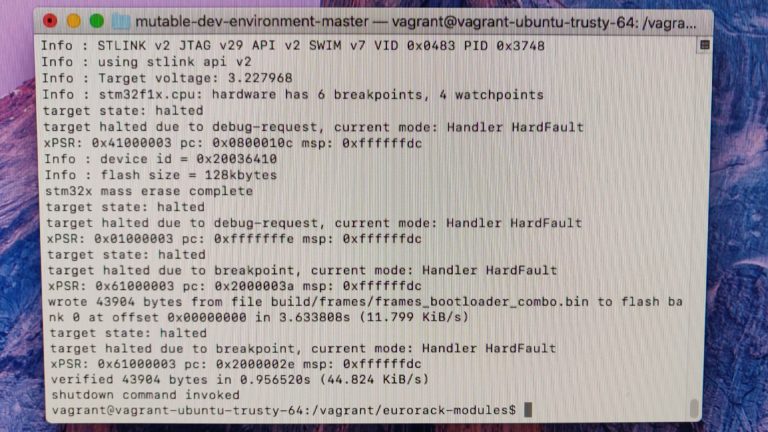
And… success! God I love seeing this text. What does it mean? No time to explain that here/I have no idea and want to maintain the illusion of understanding it. I just know IT WORKED.
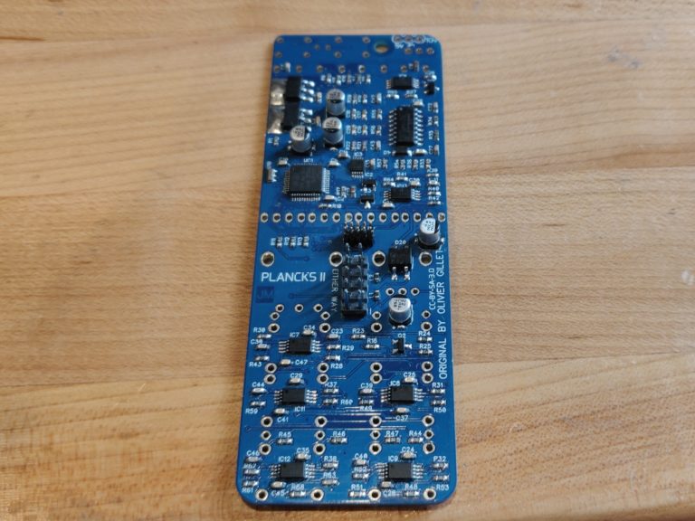
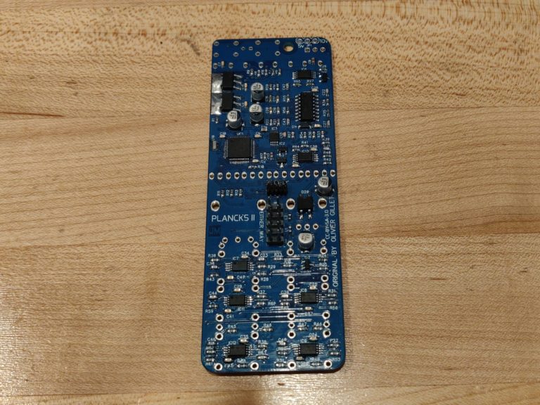
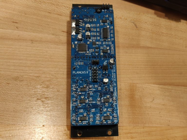
Look at it now, all flashed and ready. You can barely recognize it.
It's unreal how fast they grow up
Now that the chip is flashed and ready to go, it’s a good time to give the board another scrub. Ya ya it’s no clean solder and no clean flux… but its gotta look pretty!
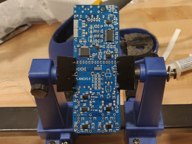
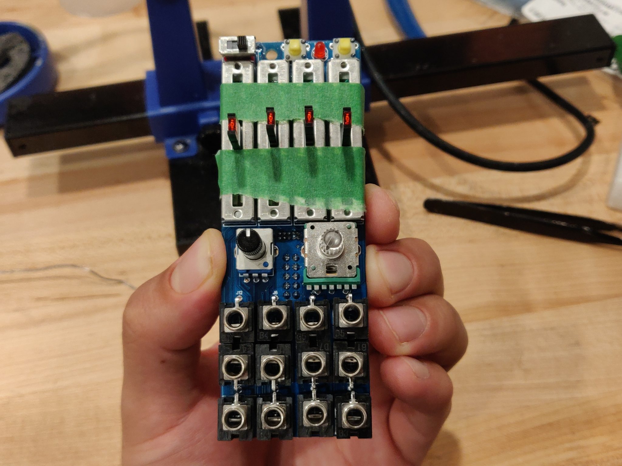
Finally, I add all of the remaining hardware to the PCB. With the slider pots I find it easiest to tape them down so they don’t move around before they’re soldered in place. Don’t forget to put the panel on before soldering the components to the board! (If you’ve read this far… I’m sure you don’t need me to tell you this)
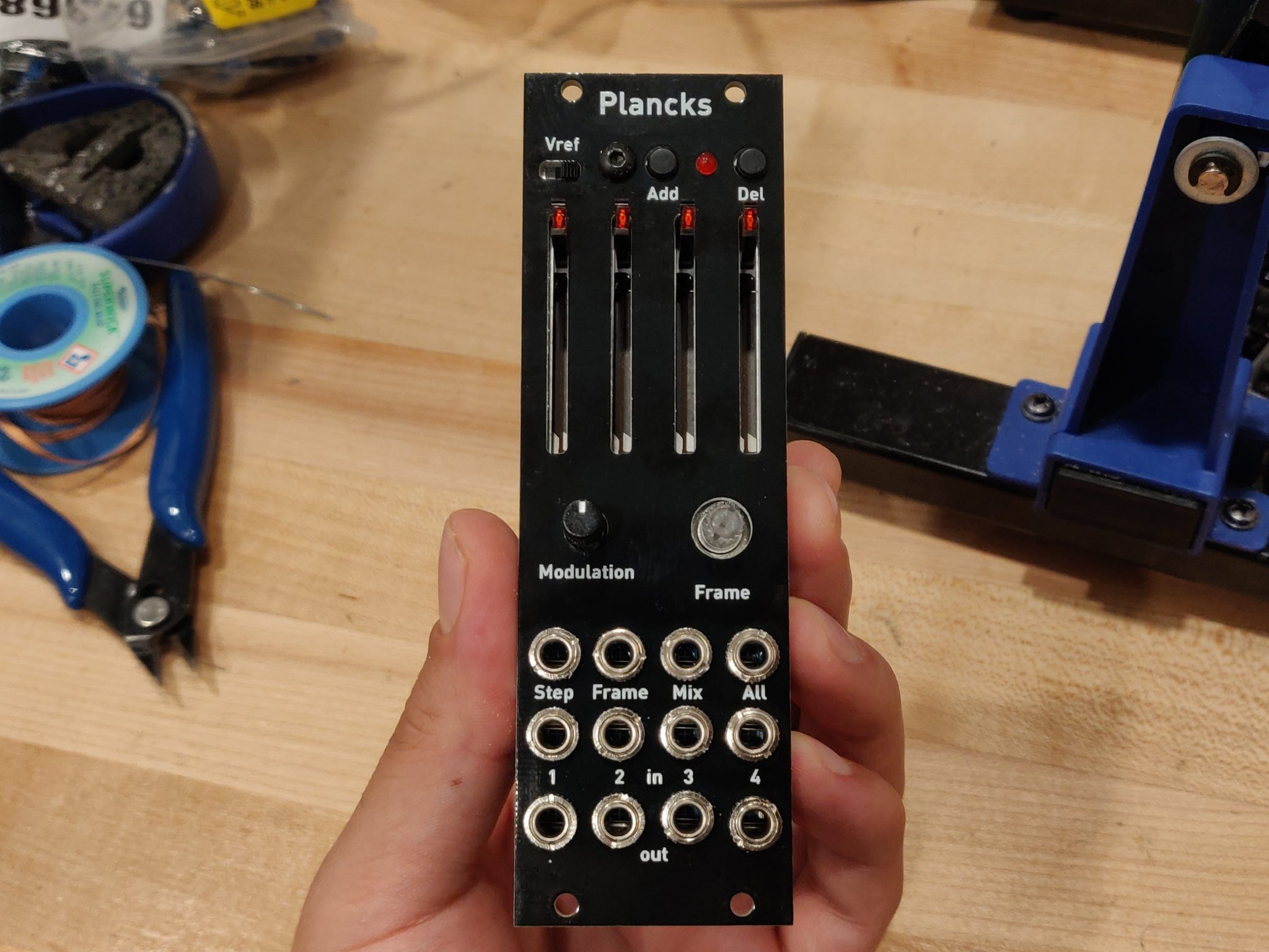
Looking good! Soldered all the hardware up…
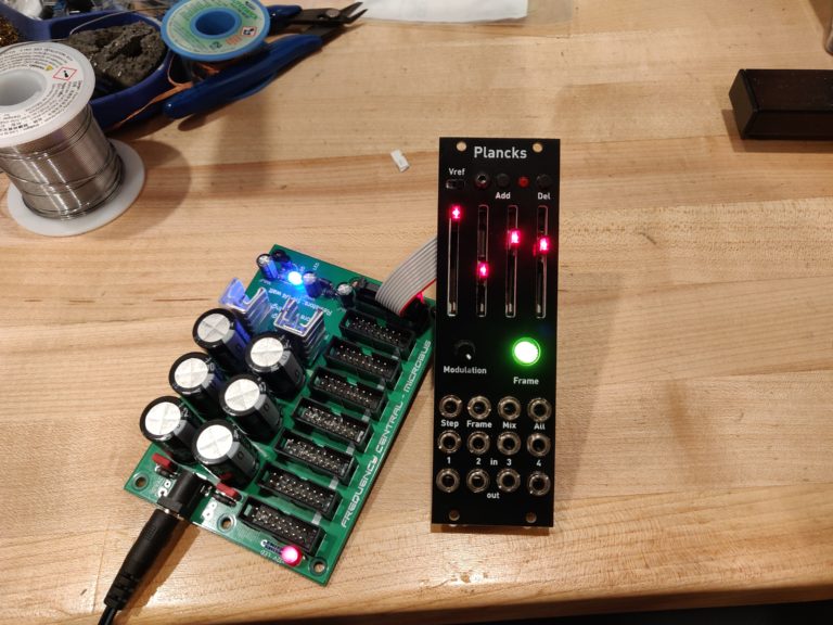
…Give it some of that sweet sweet 12V… and…
WE HAVE LIFE.
Eventually I am going to purchase some neoprene fabric to protect the potentiometers from dust. Or at least that is what I keep telling myself.
Here is the Mouser BOM I created and used for the project. This BOM does not include the SSM2164S Quad VCA, the red LED up at the top, the 3.5mm Thonkiconn jacks, or the B10K Song Huei vertical potentiometer. I also take no responsibility for what you order using this BOM. It worked for me, YMMV.
Thanks a bunch to Jakplugg for the great redesign. They’re a fellow Canadian too, gotta like that. I have built the uO_c based on their designs as well. So many beauty modules, made tiny! Going to be doing a build diary of Threshold very soon as well. Stay tuned!
Thanks for reading! It’s a great module, I’ve got my fingers crossed for you as well. Let me know if you have any issues or questions, or how much you’re enjoying it!

Thanks for this. Almost have mine all together and the firmware flashed last month. Here’s hoping it works!
Thanks for reading! It’s a great module, I’ve got my fingers crossed for you as well. Let me know if you have any issues or questions, or how much you’re enjoying it!
Hi Steve – great walkthrough! I’m about to build two Planks II and found your blog.
I’m going to start with your Mouser cart too – thanks!
Awesome, the cart is a little old, but good luck with your build!