It’s like Plaits, but it’s Antumbra working their magic again for this cute little KNIT. How did it all go? Perfectly, thanks for asking, Antumbra’s redesigns are made for simpletons such as myself. It’s paint by numbers for Eurorack, and boy am I running out of money! LETS GET SMOKEY.
Prepped and ready for sexual doctor.
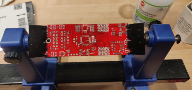
This little guy right here is the brains of the operation. Generally Antumbra builds are separated into these cute motherboard/controller board combos. Which is great for some things, but these designs also lead to me over checking these connections with my multimeter due to my severe PCBOCD.
Be sure to talk to someone if you are experiencing PCBOCD. It’s important, even if it isn’t leading to shorted connections, on your boards or in your real life.
Sorry. Moving on.
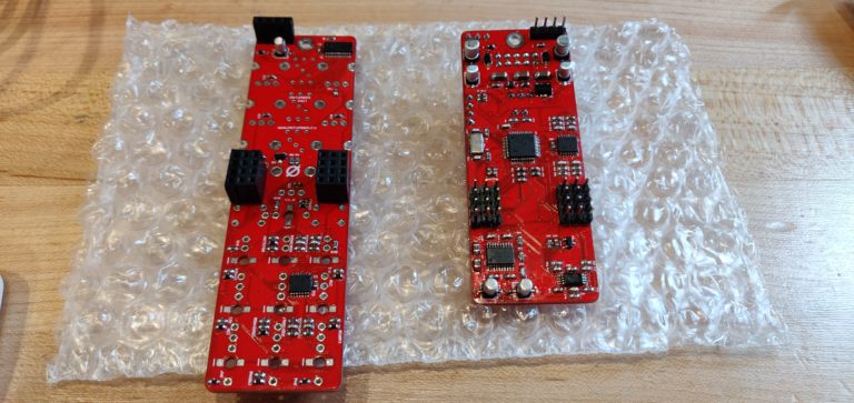
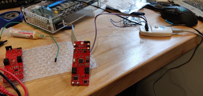
All ready for flashing, and a lil PCB scrub.
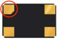
Antumbra KNIT is a tight little build, it crams all of that gooey oscillator goodness into 6HP, and it’s still skiffable with a 30mm depth. But, the only thing that is rough for us hand-solderers is the crystal.
First, my method involves painting a little solder paste on to the back of the crystal with a toothpick. For this particular crystal, an 815-ABMM2-8-E2T, I put a little on every pad except the first pin/pad on the crystal. For this pad (circled below) I left it clean, and presoldered the PCB where it would sit.
It doesn't really matter which pad you leave clean, but leaving pin 1 clean just makes it easy to remember
Next, plop the crystal down, and heat the solder that is already on the PCB. Once it is sitting properly, let the solder cool, and then apply heat to every other pad while holding the crystal in place. This is where our little Bob Ross painting adventure from earlier pays off. The solder paste will reflow from the heat of your iron, and you will have one well soldered little crystal, with no reflow oven or SMD rework station!
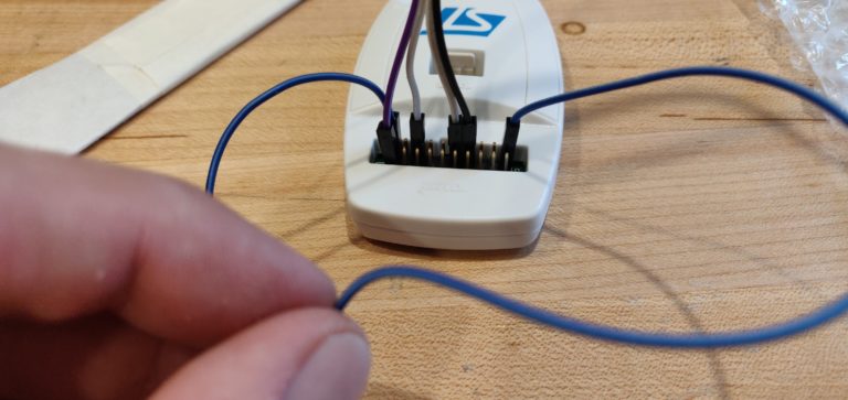
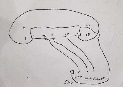
This is the pinout I use for flashing with SWD on the ST-Link V2
And finally, flashing with the ST-Link V2 is pretty simple for these sorts of builds. JTAG is always nice because I don’t have to pull out my jumper cables. You could read the manual and come up with this pinout on your own, but why not steal it from me, or Andy over at Andy’s Homemade Guitars! Andy goes by forestcaver on the internets. Thank goodness for him and his brain, or my CARA’s would be so terribly uncalibrated.
Anyways… here is the wiring diagram for programming SWD devices I stole from him.
You-Da-Man-Dy.
She flashed up no problem, as pictured below. Remember, while you have to supply power to the chip separate from the flashing interface, always make sure you’re not powering your module from two separate places. Some flashing interfaces provide all the juice the chip needs, and getting your Eurorack power involved is just going to get things SMOKEY. And not in a good way.
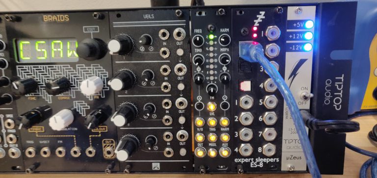
And that is about it, my nonexistent beautiful young reader. Thank you for coming along this journey with me. The Antumbra KNIT, look at it glow.
All those sweet sweet digital waves, ready for wigglin'.
Keep those mouses on swing my virulent hoard of loyal readers. Is anyone out there?
Is there calibration necessary for these guys? I flashed mine and fired it up this morning and it works, but after a couple octaves it just wigs out. I don’t have a Mutable Tester, is that needed to set it up?
Been enjoying your entires. Been building a lot of the same modules lately it would appear. Only I built a 208 😛
Thanks for reading Kris! Appreciate it big time. And a 208 !?! You’re making me jealous!!!
You do have to calibrate the module through the V/Oct. I grabbed the instructions here from the Mutable Instruments site:
To calibrate the unit:
Disconnect all CV inputs.
Connect the note CV output of a well-calibrated keyboard interface or MIDI-CV converter to the V/OCT input. Leave all the other CV inputs unpatched.
Press both buttons (A). The first LED slowly blinks in green.
Send a voltage of 1.000V to the V/OCT input.
Press any button. The first LED now blinks in orange.
Send a voltage of 3.000V to the V/OCT input.
Press any button.
Sweet, thanks! I’ll give that a shot. Hopefully that solves it, cuz it seems to work fine i think otherwise. Also finishing up a Cara this weekend… will be in the same boat for calibration, don’t have a bench scope.
I used the STLink/v2 to flash and just used their STMCubeProg software to flash the Knit. Was dead simple. Hopefully that works for the Cara as well, and I can make the calibration changes from within there.
Drop me a line if you want photos or stories about the 208 build! 😛
Best of luck! I’m looking into picking up a new meter soon, then I’ll finally be able to get my CARAs calibrated perfectly! Rather than going for a benchtop model I think I’m going to grab this guy: https://www.eevblog.com/product/121gw/
And I’ll definitely be dropping you a line! I’d love to see some pictures/hear about the trials and tribulations.
Hey Steve, Thanks for writing this. I’m just about to undertake building one of these myself and appreciate you taking the time to write this for fellow synth junkies 🙂
It’s a fun build and a great module. Always great to hear that my silly little blog can help out a fellow synth-addict! Happy building, and let me know how it turns out!!
Hi Steve. I just came across your site. I’m working on a Knit and I’m fine with assembly portion but the flashing of the MCU is beyond me. I’ve accessed the github files and have been trying to make sense of the interfaces to upload the code. Any recommendations on a resource which gives a step by step procedure for non-technical types?
But this is a little technical. Luckily some wigglers have been discussing this in a thread over at modwiggler.com. Here is my post in that thread, which includes another user’s post which breaks down the process for you:
Hopefully this is helpful to you Mike! If you need some further assistance please drop me an email at steve@stevetravale.com. I can walk you through the process as best I can!
Thanks for the STM32 Programmer SWD pin-out. Worked perfectly on my build. Had to sub in a couple of parts due to shortages. The crystal I got the part with the same capacitance and frequency but the footprint is smaller and the caps on C4 and C5 i had the footprint was 1mm to large. I ended up bending the pads on the bottom of the caps down and soldering to the board. Loving the build reports. Keep em coming!
And nicely done! Nothing better than shoving a different footprint onto a pad and seeing it boot to life. And thank you for your kind words, I’ll get back to it one day soon!
Which LEDs did you use for the jack LEDs. I ordered some 1206 and they seem to be too small. I put them all on KNIT and ATN8 and neither work. I used APTR3216SYC. Any tips would be much appreciated.
Hi steve im in the process of building one of these and i have tried to connect to forestcavers calibration proceedure on several pc’s but all we get are PAGE 404 errors.
Any ideas why that would be.
Regards Gerry – Birmingham.UK
Hey Gerry! Sorry for the late reply. I’ve had trouble finding forestcavers calibration method as well since his github went down… I’m not sure if wayback machine/internet archive would help.
With that being said, it looks like this link here down near the bottom gives some information that would be helpful!
Is there calibration necessary for these guys? I flashed mine and fired it up this morning and it works, but after a couple octaves it just wigs out. I don’t have a Mutable Tester, is that needed to set it up?
Been enjoying your entires. Been building a lot of the same modules lately it would appear. Only I built a 208 😛
Thanks for reading Kris! Appreciate it big time. And a 208 !?! You’re making me jealous!!!
You do have to calibrate the module through the V/Oct. I grabbed the instructions here from the Mutable Instruments site:
To calibrate the unit:
Sweet, thanks! I’ll give that a shot. Hopefully that solves it, cuz it seems to work fine i think otherwise. Also finishing up a Cara this weekend… will be in the same boat for calibration, don’t have a bench scope.
I used the STLink/v2 to flash and just used their STMCubeProg software to flash the Knit. Was dead simple. Hopefully that works for the Cara as well, and I can make the calibration changes from within there.
Drop me a line if you want photos or stories about the 208 build! 😛
Best of luck! I’m looking into picking up a new meter soon, then I’ll finally be able to get my CARAs calibrated perfectly! Rather than going for a benchtop model I think I’m going to grab this guy: https://www.eevblog.com/product/121gw/
And I’ll definitely be dropping you a line! I’d love to see some pictures/hear about the trials and tribulations.
Hey Steve, Thanks for writing this. I’m just about to undertake building one of these myself and appreciate you taking the time to write this for fellow synth junkies 🙂
It’s a fun build and a great module. Always great to hear that my silly little blog can help out a fellow synth-addict! Happy building, and let me know how it turns out!!
Hi Steve. I just came across your site. I’m working on a Knit and I’m fine with assembly portion but the flashing of the MCU is beyond me. I’ve accessed the github files and have been trying to make sense of the interfaces to upload the code. Any recommendations on a resource which gives a step by step procedure for non-technical types?
Hello Mike! Thanks for reading, much appreciated 🙂
The main resource would be the mutable-dev-environment Github page that has instructions on how to setup and upload code:
https://github.com/pichenettes/mutable-dev-environment
But this is a little technical. Luckily some wigglers have been discussing this in a thread over at modwiggler.com. Here is my post in that thread, which includes another user’s post which breaks down the process for you:
https://www.modwiggler.com/forum/viewtopic.php?f=17&t=222686&p=3459780#p3459703
Hopefully this is helpful to you Mike! If you need some further assistance please drop me an email at steve@stevetravale.com. I can walk you through the process as best I can!
Thanks for the STM32 Programmer SWD pin-out. Worked perfectly on my build. Had to sub in a couple of parts due to shortages. The crystal I got the part with the same capacitance and frequency but the footprint is smaller and the caps on C4 and C5 i had the footprint was 1mm to large. I ended up bending the pads on the bottom of the caps down and soldering to the board. Loving the build reports. Keep em coming!
Of course!! Glad to hear it helped.
And nicely done! Nothing better than shoving a different footprint onto a pad and seeing it boot to life. And thank you for your kind words, I’ll get back to it one day soon!
Hi Steve
Which LEDs did you use for the jack LEDs. I ordered some 1206 and they seem to be too small. I put them all on KNIT and ATN8 and neither work. I used APTR3216SYC. Any tips would be much appreciated.
Hi steve im in the process of building one of these and i have tried to connect to forestcavers calibration proceedure on several pc’s but all we get are PAGE 404 errors.
Any ideas why that would be.
Regards Gerry – Birmingham.UK
Hey Gerry! Sorry for the late reply. I’ve had trouble finding forestcavers calibration method as well since his github went down… I’m not sure if wayback machine/internet archive would help.
With that being said, it looks like this link here down near the bottom gives some information that would be helpful!
Link to Mutable Manual With Calibration Steps