It’s a rainy night in Los Angeles that feels like Japan. Robot people are out there, and there’s, like, maybe this robot guy who’s hunting the other robots? We’re not sure. Voight-Kampf is a funny sounding compound word, but you don’t care about that. You’re wondering what’s making that BWWWOOOUWWWAHHHH sound in the background. Why does this film rock so hard? Sure, Han Solo is moody, and that’s sick, but it’s GOTTA be that sweet sweet soundtrack.
What on earth am I talking about? Maybe I’m just trying to fill some space because the first part of the DIY Deckard’s Dream blog isn’t the most heart-pounding build diary entry? Or maybe I’m a literary hopeful?
It’s the former.
HO LI. Anyways, welcome to Sunday folks. I’ve been working hard on my DIY Deckard’s Dream build. I’ve been soldering for what feels like the entire lifespan of a replicant, and I’m about 1/4 of the way there. Let’s chat aboot it. (“Aboot” is Canadian for “About”).
SMD For Days
This build has been a slog so far, but like any build, it’s been a bundle of fun. I’ve soldered 593 SMD caps and cute little power IC, and I’m just about reader to throw my tweezers into a dumpster fire.
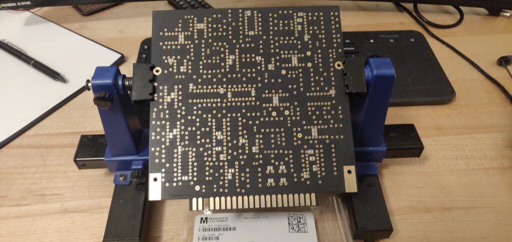
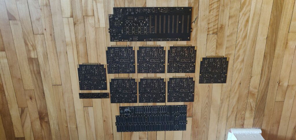
It was quite the feat. And I didn’t do myself any favours by testing continuity between the SMD caps and their connection points. Also I tested to ensure the SMD caps didn’t have continuity across their own pads. When you’re soldering SMD it can happen that a little extra solder gets stuck between the pads, and when you have a 593 of those… well I figured better safe than sorry.
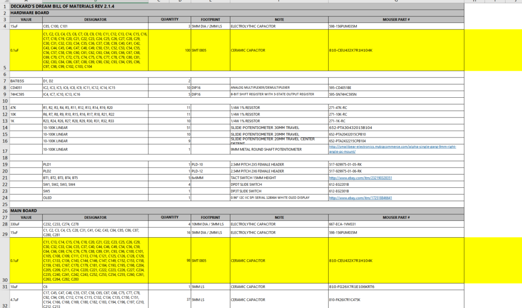
With all these parts I figured it would be best to stay organized. Not that this is revolutionary, but I am keeping a spreadsheet so I don’t loose my mind.
Getting Started on the Through Hole
Now that the SMD is behind me, I just have to hike the Mount Everest of through hole components, totalling over 2600 parts. HO. LI.
But first, because I’m a good little boy, let’s make sure they put the right parts in the right bags!
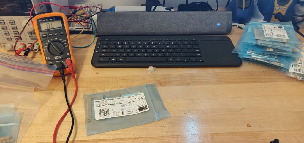
You may think I’m a little kooky for doing this. You may wonder why I don’t just look at the bands on the resistors. But I’ve got two answers for your two questions.
First, I am a little kooky, and you love it. And clearly you’ve never placed a wrong part in the wrong place because it was mislabeled. It’s a nightmare.
Second, testing with a multimeter is just so much faster.
MOVING ON.
After all the resistors we’re checked and ready to rock, it was time to take a deep breath, and start the through hole soldering.
I have mentioned this before, but I really do prefer SMD soldering to through hole. To me, it seems harder to ensure you have a proper joint with through hole parts. Cold joints are way more likely when I’m soldering through hole, and I just felt like I needed to complain a bit, OK reader? Get off my back for a second, GOODNESS. Don’t leave, I’m sorry, I didn’t mean it.
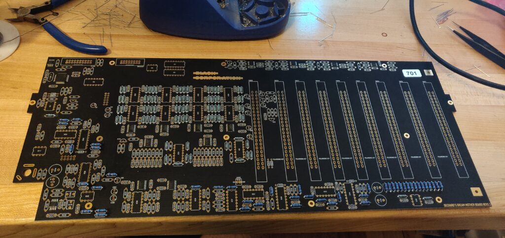
It really has been a blast even though I’ve mostly been complaining this whole post.
OH OH, this is important.
THIS IS ACTUAL INFORMATION YOU SHOULD READ.
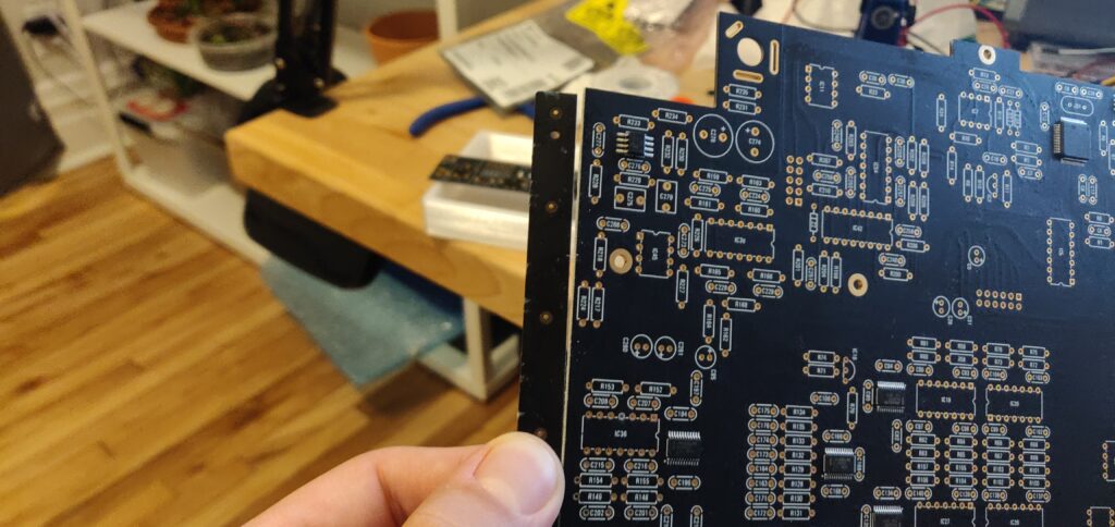
You have to remove the excess PCB on either side of the motherboard. I very much recommend you do this before you start soldering things onto the board. The stress you need to put on the board isn’t a lot, but better to not to disturb the joints you’ve already made when you can just tear this stuff off at the beginning!
The board is already scored so it is up to you whether or not you wish to run an exacto knife over it again. Mine came off pretty easy.
Take a pair of pliers, or your fingers, and gently bend the excess PCB back and forth starting at one end moving inch by inch toward the opposite end.
Cleaning up my Mess
Now this isn’t really the biggest deal, but I really want this build to go well. With my through hole soldering technique (start on the top, finish up on the bottom), there can be a little excess solder sometimes. I do my best to keep it to a minimum, but I guess I was a little excited and I really globbed it on in some places.
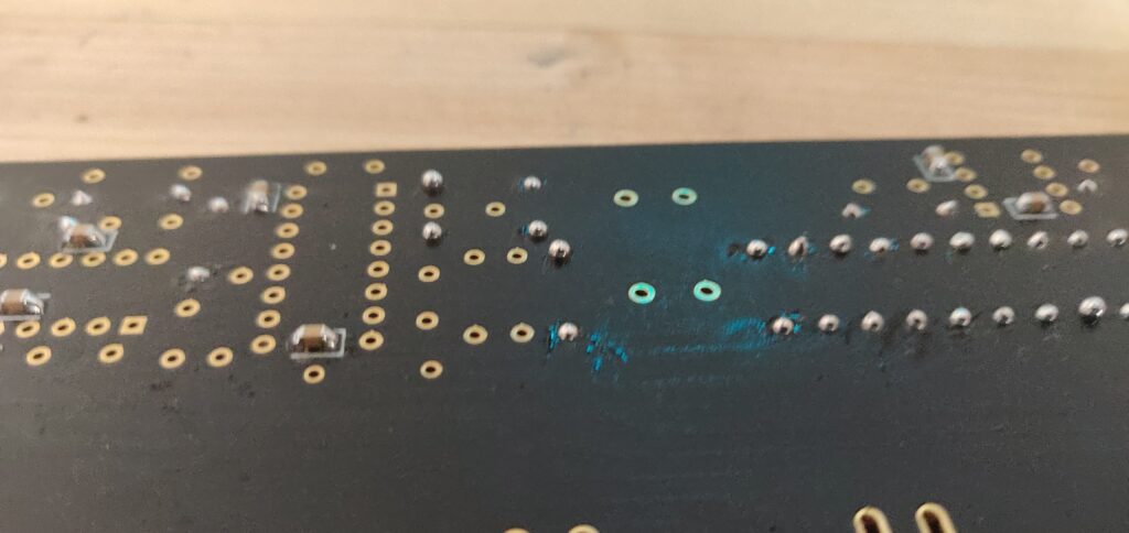
Again, this really isn’t a big deal. Because these joints are soldering from the top and bottom, the joint is most likely solid.
BUT, with this big old ball of solder on the back side, you can’t really tell if the joint is solid.
So, being the kooky lil’ Canadian boy I am, I took a wick and soaked up a whole bunch of solder. Now things are nice and clean! Thank goodness, no one wants a dirty solder-globbed Deckard’s Dream.
Part 1 COMPLETE
And that’s it for the week folks! Sure, it didn’t feel like a lot, but OH MAN it took a while. I’ll be sure to slow down on the solder for the rest of the build so I don’t have to spend time going over all the joints again. I’m hoping by next week I’ll have the motherboard soldered up, and we’ll be able to test the power rails! Exciting times! Not sure the part two of this series will be posted by then, but hey, gotta keep you on your toes my stalwart young readers.
Keep your eyes peeled. Typhoon is going to get built one of these days, and I’m DIYING (DIY-ing?, like dying, get it?) to get a Norns Shield built for a Raspberry Pi. But I should slow down.
Want something else to keep your eye holes occupied while you pretend the world isn’t burning around you? Check out my Conductive Labs NDLR Review, or if you want some solder action, check my SSSR Kotelnikov Build. Lot’s of fun stuff on the old Stevie-T blog.
Until next time, keep it samesies my friends, and have a beauty week.
OH, one last thing. My band released our first album last week. Check out the track-by-track we did for New Noise magazine, and take a listen below!

awesome