Projects with screens just feel better when they work, and the DIY Teletype is no exception.
That’s it.
Thanks for reading everyone!
What a joker I am. Stay on the edge of your seats Eurorack and DIY enthusiasts! THIS BLOG IS TRICKY.
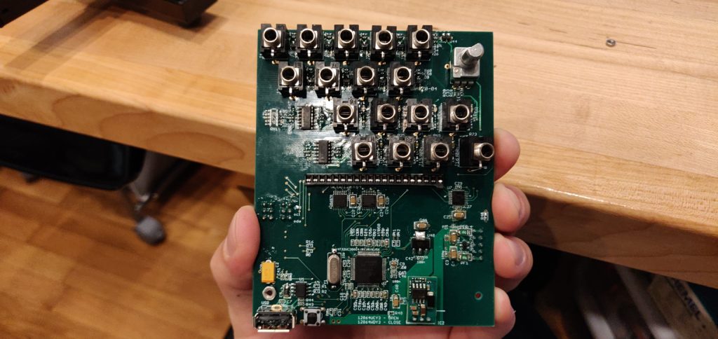
Sorry, I’ve got quarantine brain. But we all do, and that makes it feel better? Mouser is still delivering real fast, so I wasted very little time getting the missing 0402 100n caps in place.
Ahhh finally complete. With all the fixin's... Kinda. Hardware hasn't been soldered yet.
It’s a tight build in some spots, but now that I’ve done a good chunk of 0402 passives, 0603’s seem chunky. 1206? Might as well use plumbing solder.
But nothing I’ve seen thus far is as tight as the 4MS SMR build, so no complaints as far as the board layout. And now that that everything is down, I can definitively say this thing’s a beaute.
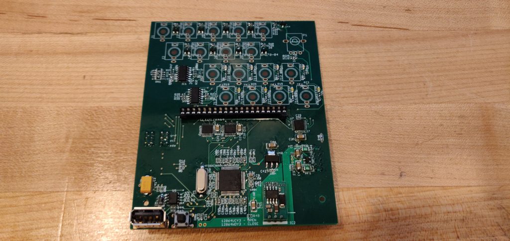
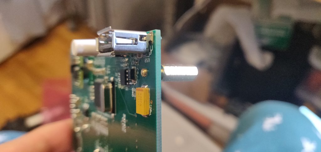
One small note on the OLED header. I ended up using half an IC socket, like I did in the Westlicht Performer build. The BOM specifies these DIP sockets, which look real sturdy and well built, but they just didn’t fit my build. The display sat way too high, even after trimming down the pins.
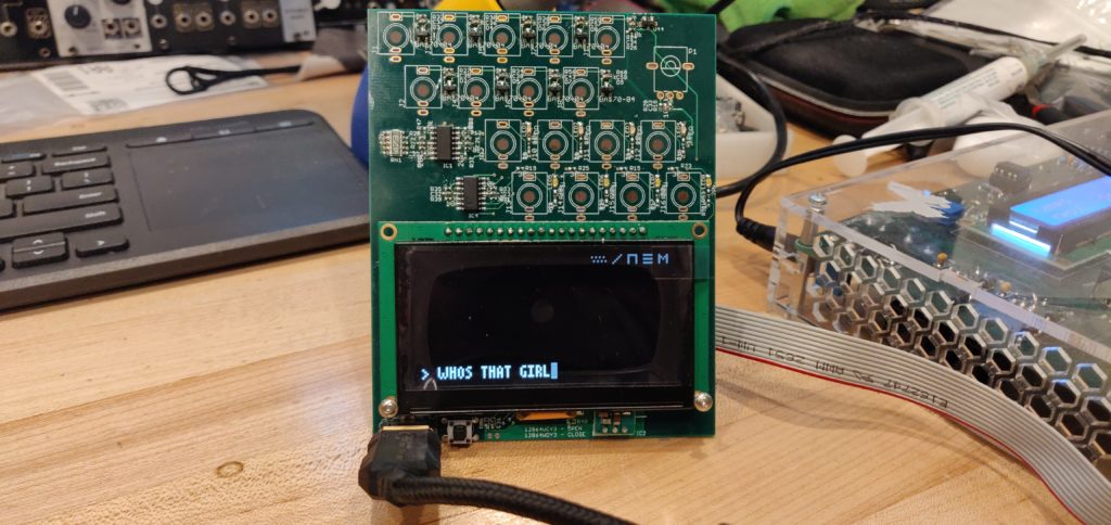
Before the hardware went down I had to flash this puppy. Look at it. SO flashed and ready to go.
Also have to say the flashing process was dead simple. So simple I spent about an hour looking for another method. I had assumed the update process for flashing firmware couldn’t be the same as the initial flash… right?
Don’t waste time like I did. It’s barely a process. And if you don’t want to hear it from them, here it is straight from the DIYers mouth fingers.
Power up Teletype holding the push button to boot the MCU into the bootloader.
Your computer will setup the new device, go to Device Manager and update the drivers manually, pointing to the driver folder included with dfu-programmer when prompted. Don’t try to skip installing the proper drivers, or dfu-programmer will throw errors.
Copy the teletype.hex (found in the teletype.zip file) file into the same place you downloaded dfu-programmer.
Open a command prompt, navigate to the dfu-programmer executable, and run the following commands one at a time:
The "whos that girl" command is some high level Teletyping, I wouldn't expect you to understand.
You don’t really have to do the first “erase” command. But hey, better safe than not Teletyping.
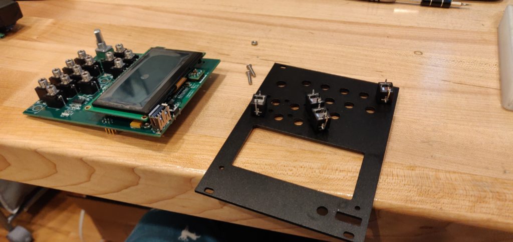
And that was the end!! Well… Kinda. There were a couple hiccups in the final stages. First, I didn’t think about how heavy the OLED was, and the front panel came tumbling off with a few jacks I had tied off to keep everything aligned while I soldered down hardware… Can’t slam your hands on the desk when you’re working with SMD parts… so I took a photo out of frustration.
No thonkicon jacks were harmed in the making of this Teletype.
Working through this tragedy, I realized my M2.5 nuts and spacers weren’t going to fit the PCB to secure the PCB to the panel and OLED… And there was no chance I was about to go back to Mouser this soon… So I did something I’m not proud of. I did something I don’t suggest you do unless there are no other choices. I had other choices. Forgive me.
Just kept twisting with pliers until my M2.5 screws fit! Not the best idea.
Terrible.
Now some people I’m sure are thinking “well, that’s not that big of a deal”. And you’re not wrong, but you ain’t right feller.
First, these mounting holes weren’t too close to any traces in the PCB, making it less likely to cause damage widening the hole a bit.
Second, the increase in size really wasn’t that big of a difference. The less stress on the PCB the better
So the risk wasn’t too high in this case, but a lot could have gone wrong. I could have cracked the PCB. I could have damaged solder joints from the amount of torque I was torquin’. I could have flung it across the room if I wasn’t careful.
All in all, maybe not the riskiest move you can pull, but definitely not a move you want to pull. Go and grab the right parts:
mcmaster: 91780A023, 91772A077, 91772A073
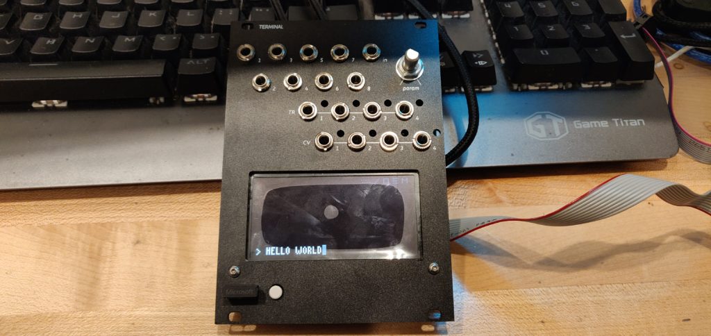
Either way, look how nice it looks now, good and stable!
Also, my wireless Microsoft keyboard works with this thing. HOW COOL IS THAT.
No, I am never removing the plastic protection, and yes, this diary is over without installing light pipes for the LEDs. I FORGOT TO ORDER THEM TOO.
Hi there!I am amazed by your diary.I need to build a frontpanel for teletype,the factory told me I have to offer cad files,but I only find open-source pdf file for the panel.Could you please tell me how you get the panel when diy teletype?
I can’t seem to find what pot to use for P1, can you let me know?
Hey there! Thanks for reading. For P1 you will want to use a 10k Alpha Pot.
I’m getting ready to start on one soon. Your build diaries are super helpful!
Thanks Bryan! Appreciate your comment 🙂 let me know if you have any issues or questions with your build!!
Hi there!I am amazed by your diary.I need to build a frontpanel for teletype,the factory told me I have to offer cad files,but I only find open-source pdf file for the panel.Could you please tell me how you get the panel when diy teletype?
Hey there! I bought mine from pusherman, here’s a link:
https://pushermanproductions.com/product/terminal-teletype-black-anodized-aluminium-panel-only/