DIY Bluetooth MIDI Pedal

Stevey got some new plugins, and in order to properly control these new plugins, Stevey wanted a bluetooth MIDI pedal.

But, Stevey couldn’t find a pedal that felt right, or didn’t cost an arm and a leg. So, Stevey got to work on a DIY Bluetooth MIDI Pedal.

Sorry, I’ll stop talking stupid. I got a gnarly new NeuralDSP plugin (happy Black Frid-eh, that’s what we call it in TGWN) and I want to be able to program some MIDI parameters to make my life easier. But what am I supposed to do… STEP ON MY KEYSTEP? What a nightmare. But where there are nightmares, there are geeky solutions.

Prototyping with Adafruit

Circuit Playground Bluefruit
Circuit Playground Bluefruit to the rescue...Maybe?

It started like all projects; low and slow, like a pulled pork. I went into the old trinkets drawer and pulled out a Circuit Playground Bluefruit. This little guy is a great learning device with everything I need built in, so we started with a mostly stolen script in CircuitPython. Thank you to this website here, I borrowed some of your lines homie.

import time

import board

import digitalio

# Midi
import adafruit_midi
from adafruit_midi.note_off import NoteOff
from adafruit_midi.note_on import NoteOn

# BLE Midi
import adafruit_ble
from adafruit_ble.advertising.standard import ProvideServicesAdvertisement
import adafruit_ble_midi

# Setup Button
button_a = digitalio.DigitalInOut(board.BUTTON_A)
button_a.direction = digitalio.Direction.INPUT
button_a.pull = digitalio.Pull.DOWN

# Setup BLE Midi
midi_service = adafruit_ble_midi.MIDIService()
advertisement = ProvideServicesAdvertisement(midi_service)
midi = adafruit_midi.MIDI(midi_out=midi_service, out_channel=0)
ble = adafruit_ble.BLERadio()

# Make BLE Device visible
print("Waiting for BLE MIDI connection")
ble.start_advertising(advertisement)
while True:
# If not connected, don't execute the rest of the code
while not ble.connected:
pass

print("Connected")
while ble.connected:
midi.send(NoteOn(70, 127))
print("NOTE ON")
time.sleep(1)
midi.send(NoteOff(70, 127))
print("NOTE OFF")
time.sleep(1)

# If disconnect, wait for reconnection
print("Disconnected")
print("Advertising BLE")
ble.start_advertising(advertisement)

#credit to https://www.electromaker.io/project/view/circuit-python-ble-midi-on-windows

Nothing too sassy here. The device will attempt to create a bluetooth connection, and when it does it sends a MIDI note on message, then a MIDI note off message. There’s also some code in there for a button I implemented. But I forgot to save the actual implementation to my computer before overwriting the Bluefruit with something else… But, it won’t matter soon… BECAUSE WE THROW THIS CODE TO THE CURB LIKE ITS TRASH NIGHT AT GOOGLE.

Once it worked the way I expected, I.E. the button made a note come on and it wasn’t too wildly delayed, it was time to move on from the Circuit Bluefruit Playground.

Back into the trinket drawer, and I found a Raspberry Pi Pico!

It's Pi Time for Pedal Boy

Raspberry Pi Pico

Noice!! Got it all soldered up and ready to roll… but dumby me thought it had bluetooth already on board. It does not.

So, back to the trinket drawer. And lucky me, I found an HC-05 bluetooth module (the trinket drawer was Amazon in this case). This is a cute little chip that will add bluetooth functionality to your project. So I got it all snuggled into my breadboard, and got to writing the code.

Breadboarded Raspberry Pi Pico
So much board, so little bread.

Forgive me again, because things got weird here, and I didn’t save as often as I should have. But, as I started writing the code I realized this would be no where near as simple as it was on the Adafruit chip. I wrote a simple script that connected to a device and allowed serial messages to be received… but program changes were a little more complicated than they were on the Adafruit chip.

Adafruit creates tons of libraries for their devices, and while you can use them on other devices, things don’t play as nicely all the time. I first tried Blinka, which brings the Adafruit libraries that made everything so easy to the Pi Pico.

This was a nightmare. Likely of my own making, but I’m not a software boy. So, after Thonny installs, and uploading/managing space for libraries… and failing… we dive back into the trinket drawer.


DIY Bluetooth MIDI Pedals need ESP32s

ESP32 on Breadboard
And we find an ESP32!

I decided to move onto an ESP32. The ESP32 has bluetooth built in, and is a widely used device. This means I can easily steal code from others. Stealing is the only way things get done, anyone who says any different isn’t aware of their THEFT, or they got them big brains.

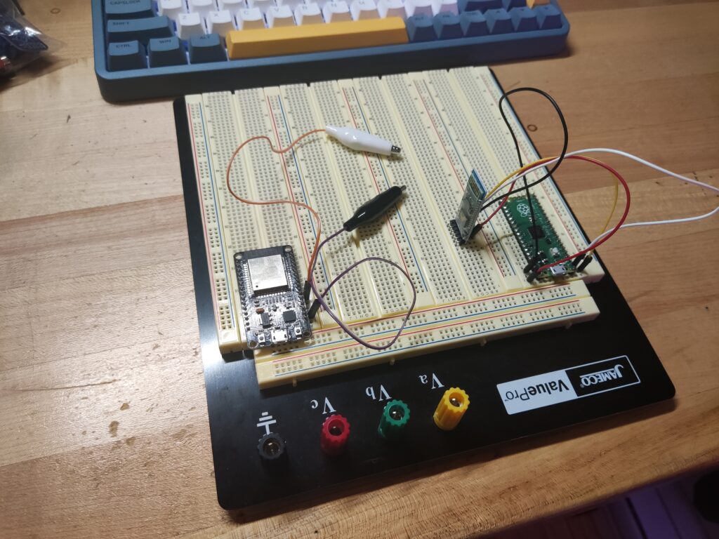
With the ESP32 breadboarded, I whipped up the following bit of code to handle what I need from the device.

#include <Arduino.h>
#include <BLEMidi.h>
#include <ezButton.h>
#define BUTTON_PIN1 16 // ESP32 pin 16 (RX2),connected to button
#define BUTTON_PIN2 17 // ESP32 pin 17 (TX2), connected to button
#define BUTTON_PIN3 4 // ESP32 pin 4 (D4), connected to button

ezButton button1(BUTTON_PIN1);
ezButton button2(BUTTON_PIN2);
ezButton button3(BUTTON_PIN3);
boolean connectedMsg = false;

void setup() {
Serial.begin(115200);
pinMode(BUTTON_PIN1, INPUT_PULLUP);
pinMode(BUTTON_PIN2, INPUT_PULLUP);
pinMode(BUTTON_PIN3, INPUT_PULLUP);
button1.setDebounceTime(50);
button2.setDebounceTime(50);
button3.setDebounceTime(50);
Serial.println("Initializing bluetooth");
BLEMidiServer.begin("Basic MIDI device");
Serial.println("Waiting for connections...");
//BLEMidiServer.enableDebugging(); // Uncomment for debugging

}

void loop() {
if(BLEMidiServer.isConnected()) {
if (connectedMsg == false){
connectedMsg = true;
Serial.println("*****CONNECTED*****");
}
button1.loop();
button2.loop();
button3.loop();
if (button1.isPressed()){
BLEMidiServer.programChange(0,0);
Serial.println("P1 CHANGE SENT");
}
if (button2.isPressed()){
BLEMidiServer.programChange(0,1);
Serial.println("P2 CHANGE SENT");
}
if (button3.isPressed()){
BLEMidiServer.programChange(0,2);
Serial.println("P3 CHANGE SENT");
}
}
}

Big thank yous for the BLEMidi library from Max22 in this code. The documentation wasn’t the best… or existent really, but the code was written well enough I could decipher how to make program changes.

We’ve almost got ourselves a DIY Bluetooth MIDI pedal at this point!

Now that the software was good to go, it was time for the fun stuff! 3D printing and slappin’ it all together.

It started out simple. A nice little box with an area for all my little junks. I borrowed the step-up converter, battery charger, and batteries out of the spares I had from the battery-powered EUROBURO project (which will be complete soon!!).

3D Printing Fun (it wasn't fun)

3D Printed Panel Square
Needs some adjustments, but that's what gold markers and PETG is for.

Sadly my 3D printer had a little hiccup. Or, rather, I learned that PETG needs to be quite a bit further from your print bed to print properly. After that little snafu and another trip to big-daddy-Bezo’s web shop for a new print bed, we got to prototyping.

Many 3D prints
The progression...

First I had to flip it because I’m a dumb dumb. Then I had to widen out the wire channels a little more… And then, I realized that the squareness of the 3D model was, first off, kinda gross, and second, causing problems during the print.

So, we rounded that puppy out.

Rounded Bottom Part
Noice, much cleaner print too. BUT UH OH!?

SWEET. Nice, round, and good to go. RIGHT?

WRONG, my dear reader. The more keen eyed among you may have noticed that the cavity for the step converter comes before the cavity for the USB-C battery charging PCB… It needs to be the other way around. But you come for that messy DIY drama, don’t you?

Completed bottom piece
MUCH BETTER.

Another small issue arose. I kept getting layer shifting on my prints. This is when the print shifts a little (or a lot) at some point during the print, causing the layers that occur after the shift to be misaligned with the others.

This issue is particularly bad with the Adventurer 3 I use, as the removable bed has a little play on either side. A print can get snagged on the print head, and it drags the bed over ever so slightly, causing layer shift. GROSS.

But, I got smart and mushed some putty onto the one side of the build plate, that way it wouldn’t shift any longer. I had to be careful not to push the bed down when putting the putty on, but it’s done the trick quite well for me.

Putty on Adventurer 3 3D Printer
You can see my little feetsies in the reflection.

Final Assembly

But with all of the 3D printing nonsense behind me, it was time to assemble. FINALLY.

Pieces for creating the device.
ALL OF MY LITTLE TRINKETS. ALL READY FOR THE PROM.

The soldering was quite simple here, so no fun 0402 components for everyone’s eyes to bleed over. And before I knew it, I could put the iron away, we had ourselves a circuit.

Soldering complete, box with wires hanging out.
Look at that 5v! So stable, so consistent.

Almost done! But not without one more catastrophe.

I didn’t make any holes in the 3D models for screws/inserts. I figured I would just drill holes and figure it out later. This, was a poor idea. First I just tried mushing screws into the plastic, but that didn’t work very well. 

Panicked, and not wanting to print for another 15 hours (PETG is slowwwww), I consulted a dear friend who calmly hooked me up with some knowledge.

I took this knowledge, and used my soldering iron with some cute little 2mm standoffs to melt them into the plastic. The amount of infill on the print didn’t make it too easy, but I gobbed superglue anywhere that the standoff didn’t look stable. And wouldn’t ya know it, it worked BEAUTIFULLY. Beautifully-ish.

Standoffs in casing
And they're pretty sturdy!

Lastly, I had to get all the pieces secured in the case!

For the step converter and battery charging PCB, I super-glued them down into their cavities. They were already pretty secured in their little hidey-holes, but the glue will make it a for-sure-for-sure.

For the battery, you really don’t wanna be sputterin’ just any old glue onto it. That’s begging for a bad time. Some double sided tape worked perfect for me in this situation.

Securing everything into the case
Tape is always better than a fire.

For the ESP32, I dropped it onto a piece of stripboard, soldered it up, and mounted it to a standoff which was then mounted to the topside of the case. Looking PRETTTTTY neat right about now.

Completed DIY Bluetooth Midi Pedal Insides
YASSS SO WIRELESS. On the outside...not on the inside.

I did some poor math on my 3D models, and you might be able to see I had to melt away some of the plastic to get the battery to fit. But you can barely tell!

YOU WOULDN’T HAVE EVEN KNOWN IF I DIDN’T TELL YOU SO QUIT IT, STOP LOOKING AT IT.

But anywho, that was about it! Now I have a sweet DIY bluetooth MIDI pedal that is rechargeable. It currently is setup to send program change messages, but it could send any type of MIDI message.

The only thing I dislike is that I have to go into the Audio MIDI settings on my Mac and connect it from the setup menu every time I connect… But, apparently, this is a problem with alot of bluetooth MIDI devices on Mac. SO WHATEVS.

Here are some hot shots of the exterior.

Top view of complete DIY Bluetooth MIDI Pedal
Ouu so cute and stompy.
Bottom view of complete DIY Bluetooth MIDI Pedal
I even put lil footies on there!
Back view of complete DIY Bluetooth MIDI Pedal
USB-C for recharging, and a big old toggle switch. Noice.

And that’s it, that’s all folks! It works beauty, and I hope it helps someone else out there. Or at least entertains them. ARE YOU NOT ENTERTAINED?!

I’m so sorry. Here are my STL files to make up for it.

CLICK ME FOR STL FILES.

Remember for this STL file, there are no holes for fasteners and the top half needs some parts shaved down to fit the battery. I’ll fix it one day, maybe.

Thanks for coming back, sorry I was gone for so long! Have a great week and keep it SAMESIES out there.

Leave a Reply