I get it, you’re sick of it. “Where’s part 2?” I’m sure you’re asking. “Was there ever a LYRA? Why don’t I just give up and do a LYRA-4?” Clearly, I don’t have the chops to get this Russian beauty out the door
WELL YOU’RE WRONG READER. I don’t know why you’re so grumpy today. But I’ll get to the hot takes and synth shots.
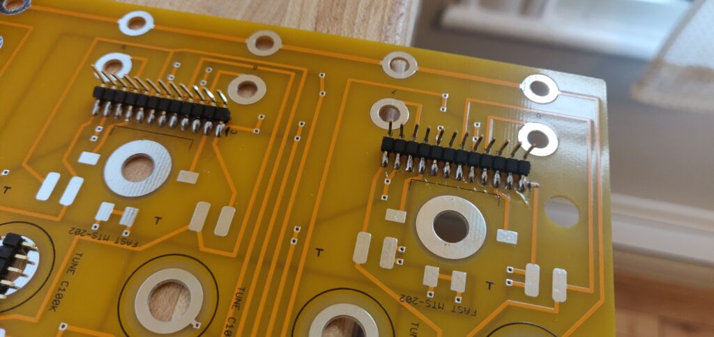
Control Board Time!
Oh control board. Are you SMD? Are you through hole? I don’t know if you’re even sure.
I was too scared to solder straight to the board.
I started by putting down some pin headers. If I had a time machine I would have purchased proper SMD headers and done it that way, these are a little janky. I didn’t want to solder the cables directly to the board, that’s too much commitment. That being said, they are making solid connections, so let’s rock on.
One weird thing for people might be soldering through hole components to the pads. Here’s how I do it.
Start with a little solder on the pad.
Place the part generally where it should be and trim the legs to fit the pad. Make sure you get the orientation right!
Now take your tweezers and your iron and grab the capacitor with the tweezers. Heat the pad with your soldering iron and gently press the lead into the pad. Try to keep it all within the pad, a leg hanging over a pad can get you shorted. Rinse and repeat!
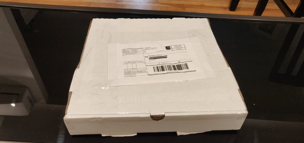
Time for a pizza break.
Starved after all this fake SMD soldering.
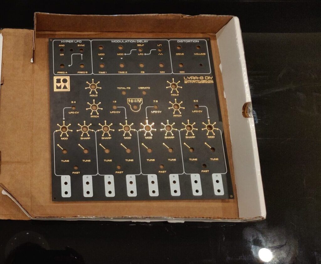
That's not a pizza! It's a panel from our friend at Flundrton.com!
Panel Time
It’s panel time! And god damn does it look good. Thank you again to MuffWiggler user flounderguts, with his stellar website over at flundrton.com. Get yourself a DIY LYRA-8 expansion set, do it now!
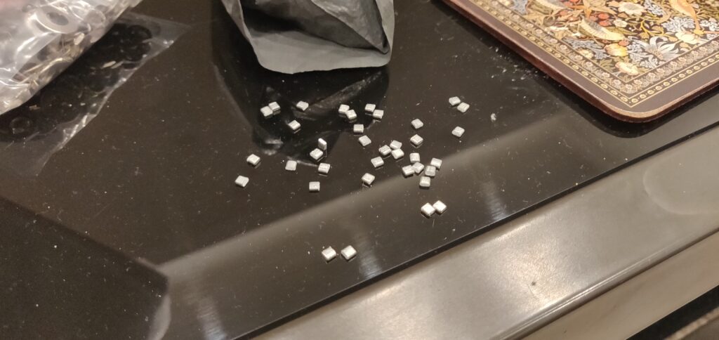
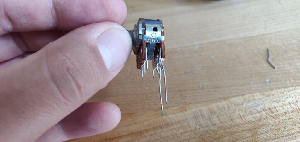
Back to blog. So this all started with me trimming far too many tabs on pots.
OK it doesn't look like that many, but it felt like it took a lifetime. WHATEVER READER.
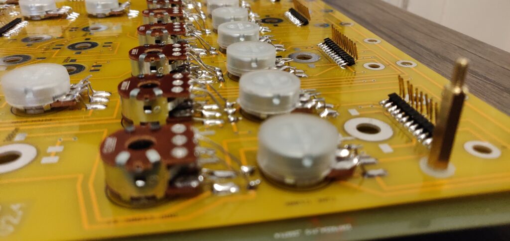
And then I got far to excited and decided to attach all the hardware to the panel. Which honestly looked so stellar. Check it.
Ouuff so sleek. What a panel.
Look how pretty and neat it looks.
It was at this point I realized I needed to mount the main board to the control board. Oopsies! That’s what I get for getting excited. 30 minutes and some very sore thumbs later, it was back apart.
Good thing, because it’s definitely best to solder legs to the pots before you mount them.
DID YOU KEEP YOUR LEADS? I DID. IM A GOOD BOY.
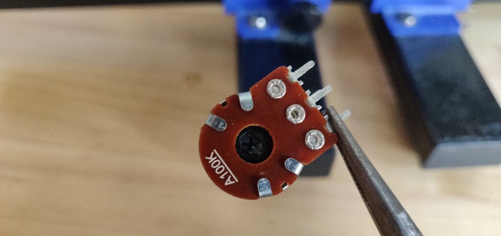
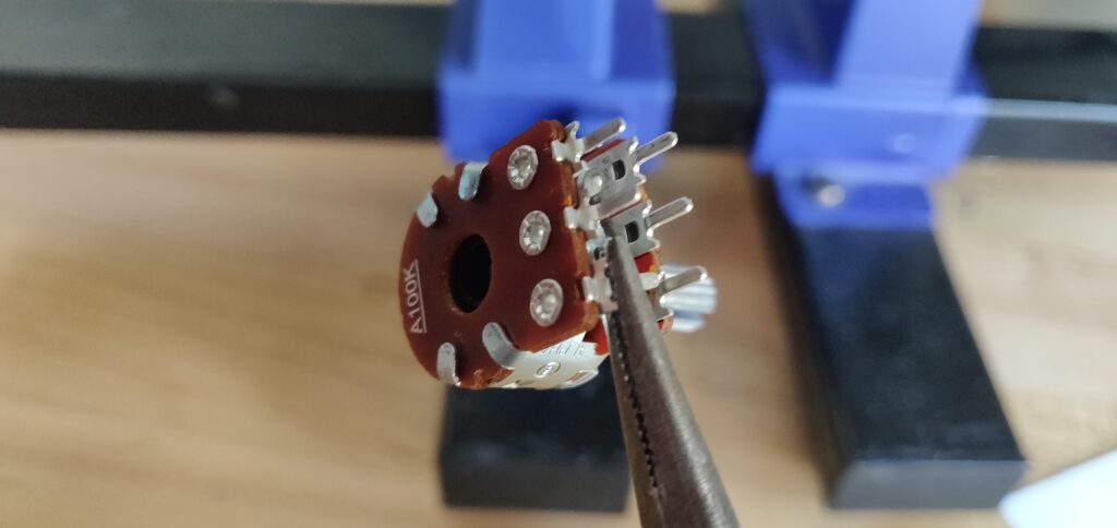
Some pots have little slots and make it easy to “extend” the legs. But if you got some of these pots with tiny little legs, especially the stereo ones, here’s a tip.
Grab the leg from the back side with some pliers.
Bend the pin back gently. There is now a small slot you can shove your lead into!
Soldered and good to go! Glad I trimmed my nails this day.
Rinse and repeat that step about almost 100 times and you’ll be ready to mount the hardware again!
Don't forget to check for continuity!
This step isn’t as necessary for the switches, so don’t worry young reader! I didn’t forget about the switches. It was just late, and I wanted to get these things melded to the board.
Artsy shot
It went very well, all things considered! A little finicky, but a good time nonetheless.
My method: bend the leads so they will press down into the board when you stick the pot in. From here, push them flush to the pad with the backside of some tweezers and screw the pot in. After soldering, CHECK FOR CONTINUITY. It’s a must.
One thing I didn’t show here, I added about 2mm worth of spacers around the board. The way I mounted the board had it sitting 2mm above the panel on each corner where the posts were. It was a problem when I started screwing the pots in; the board was flexing something terrible. So I dropped about 15 2mm spacers all over the board to keep it nice and rigid with no flex. Now it’s solid!
Until Next Time...
I promise you, my audacious reader, Part 2, the finale to our epic journey, will be complete soon. Just have to finish the switches, find some thumb screws, knobs, a case, troubleshoot and test… Anyways… it will be complete enough to make noise soon enough! Fingers crossed it boots up.
No idea how you got here? Try Part 1 and Part 1.5 of this series! They’re solid reads, at least I hope. Want something more euro-racky? How about that Threshold build from ages ago? That was a fun one, miss you jakkpluggggz.
Anyways, have a beauty week team! Keep it samesies out there and I will see you next week with a (fingers crossed) LYRA-8!
The panel looks great as does your entire build. I contacted flounderguts and have yet to hear back. The panels are out of stock but I did download the gerber files from the site. Would you have any suggestions for an outfit who could use these files to create a panel for me, drilled and printed, should flounderguts not be able to?
Thanks Andreas! Appreciate your kind words, sorry for the delay in my reply. Any PCB manufacturer should be able to print out the panel for you, the panel itself is made from PCB material, the silkscreen and exposed copper traces are what give it the design. I have used JLCPCB with much success. That being said, I would recommend waiting on flundrton.com. The cost will be much less and shipping will be quicker. If you choose to print them yourself through a manufacturer, you will likely need to purchase a minimum amount, or if you go for a place that does one-offs, the cost will be very high.


The panel looks great as does your entire build. I contacted flounderguts and have yet to hear back. The panels are out of stock but I did download the gerber files from the site. Would you have any suggestions for an outfit who could use these files to create a panel for me, drilled and printed, should flounderguts not be able to?
cheers,
Andreas
Thanks Andreas! Appreciate your kind words, sorry for the delay in my reply. Any PCB manufacturer should be able to print out the panel for you, the panel itself is made from PCB material, the silkscreen and exposed copper traces are what give it the design. I have used JLCPCB with much success. That being said, I would recommend waiting on flundrton.com. The cost will be much less and shipping will be quicker. If you choose to print them yourself through a manufacturer, you will likely need to purchase a minimum amount, or if you go for a place that does one-offs, the cost will be very high.